The electrical installation must be performed by a qualified electrician (EN 60335-1). The heating cables must feature a multi pole circuit breaker with a contact clearance of at least 3 mm per pole. To protect against inadvertent contact, an RCD (FI circuit breaker) with a tripping current of IΔN ≤ 30 mA must be installed.
Further information on installing the heating cables and installing and setting up the thermostat can be found in the respective installation instructions.
Positioning the floor sensor
Variant A: The floor sensors are positioned directly in the newly installed uncoupling mat Schlüter-DITRA-HEAT. Since the floor sensor is embedded directly in the thin-bed tile adhesive and cannot be replaced, the installation must include a spare sensor (a second sensor is included in thermostat scope of supply as a spare sensor). Place the sensors in the centre between two heating cable loops.
Variant B: Position the floor sensor of the thermostat in the conduit with the sensor sleeve directly in the floor below the DITRA-HEAT uncoupling mat. Cut an opening in the heating mat DITRA-HEAT in the area of the sensor sleeve. Insert the sensor into the conduit and slide the sleeve over it (conduit and sensor sleeve are available as an installation set, Art.-No. DH EZ S1).
To guarantee an optimal temperature transition from the heated area to the sensor, no insulation material may be located between the sensor sleeve and DITRA-HEAT. In this case, cut an opening in the insulation in the area of the sensor sleeve.
Note: Before embedding the sensors with thin-bed tile adhesive, measure the resistance values, e.g. with the cable tester DITRA-HEAT-E-CT, and compare them with the values listed in the thermostat installation instructions.
- The substrate must be level, load-bearing and free of components that may inhibit bonding. Any necessary levelling work must be completed before installing DITRA-HEAT.
- The selection of the adhesive for installing DITRA-HEAT depends on the substrate.
The adhesive must bond with the substrate and mechanically set in the DITRA-HEAT anchoring fleece. A dry setting thin-bed tile adhesive is suitable for most substrates. The adhesive should preferably have a consistency suitable for fluid beds. Review any potential material incompatibilities beforehand. If using covering materials with a side length exceeding 30 cm, we recommend a quick-setting tile adhesive with crystalline water binding capacity for fast curing and drying of the mortar.
- Apply a suitable thin-bed tile adhesive on the substrate with a notched trowel (6 x 6 mm). To achieve better initial adhesion for installation in wall areas, we recommend applying a contact layer on the reverse side of DITRA-HEAT.
- Embed the DITRA-HEAT mats, which must have been cut to size beforehand, into the installed adhesive with the anchoring fleece facing down. Immediately press them in place with a float or roller, working in a single direction. The curing time of the adhesive must be observed. For efficient installation of product rolls, precisely align DITRA-HEAT and keep the material stretched with light tension when placing it on the substrate.
The EasyCut gridlines minimise the curling memory. Mats are recommended for wall applications for easier handling. The mats or membranes are installed with closely abutting joints.
- To prevent any damage to the installed DITRA-HEAT material or detachment from the substrate, protect the area from mechanical stresses, e.g. by setting out running boards (particularly in the centre areas used for material transport).
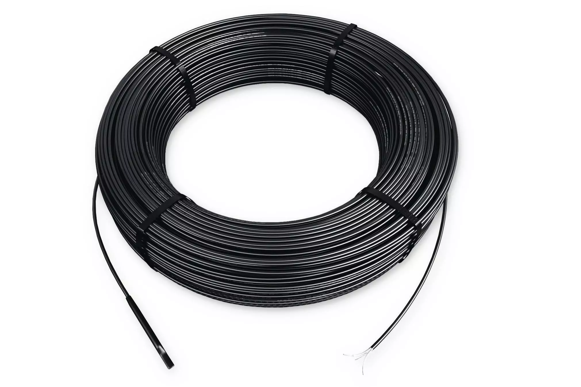
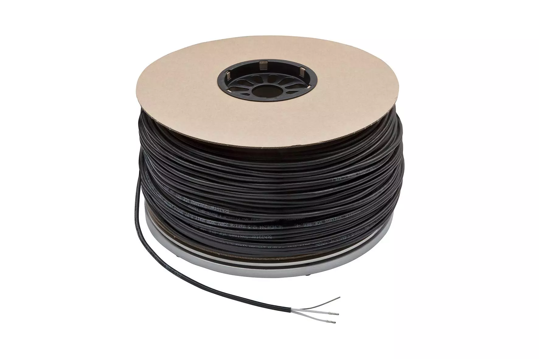
Heating cable installation
- For installation in floor areas, heating cables may be installed immediately after adhering the uncoupling mat DITRA-HEAT, using a float or roller.
For wall installation, the heating cables are installed once an adequate adhesive bond has been reached.
Heating cables must never overlap or touch each other. - Create a corresponding indentation in the area of the sealed cable end.
Note: Use the cable tester Schlüter-DITRA-HEAT-E-CT to continuously measure the resistance of the electrical heating cables DITRA-HEAT-E-HK. The device monitors the resistance of the heating cables during the entire installation phase and alerts the installer with an acoustic signal in the event of damage.
- Floor areas:
The stud spacing in the uncoupling mat is 3 cm. The installation spacing in the floor area must be
- at least 9 cm (around every third stud – the equivalent of 136 W/m²)
Closer installation spacing - especially in floor areas - may lead to overheating and can cause damage to building structures.
Avoid stepping directly onto heating cables during the installation work.
- Wall areas:
Depending on the available space, the desired surface temperature and the required heat output, the installation spacing in wall areas can either be
- 6 cm (around every second stud – the equivalent of 200 W/m²) or
- 9 cm (around every third stud – the equivalent of 136 W/m²)
- The transition from the heating cable to the connection cable (sleeve) is marked with an imprint as shown. The sleeve also has a sticker on that reads "Connection". The connection cable is labelled with the imprinted marking "COLD" further on. This 'cold leg' (4 m) must be connected directly to a junction box or thermostat. The 'cold leg' may be shortened to a max. length of 1 m before the fitting. The heating cables may not be shortened.
- After installing and checking the heating cables as specified in the installation instructions for DITRA-HEAT-E, the tiles can be installed in the thin-set method, using a thin-bed tile adhesive that meets the requirements of the respective covering. For maximum efficiency, fill the indentations of the heating mat with the smooth side of a notched trowel (heating cable and fittings must be completely embedded within the tile adhesive) and groove the thin-bed tile adhesive with the notched side of the trowel to prepare for tile installation. The notch size of the trowel must match the tile size to completely embed the tiles in the thin-bed tile adhesive. Observe the curing time of the adhesive.
- Follow the instructions in the data sheet to install movement joints for perimeter, edge and transition profiles.
Note: The cementitious tile adhesive and the covering material used in conjunction with DITRA-HEAT must be suitable for the respective application area and meet the corresponding requirements. Wait at least 7 days after completing the covering assembly to heat up the DITRA-HEAT-E system for the first time.
Note for installing DITRA-HEAT in wall areas:
To mark the heated wall space (and avoid inadvertent drilling into a heating cable), we recommend using Schlüter profiles (such as RONDEC, QUADEC or DESIGNLINE) to visually outline the corresponding area.
In the case of heated wall areas exceeding a length of 3 m, the wall and connection joints must have a permanently elastic design to accommodate thermal expansion.
Thermostat:
The heating cables of the DITRA-HEAT system may only be operated with DITRA-HEAT-E thermostats.